Monday, May 22, 2024

How to Size Industrial Dust Collection CFM for Real Shop Conditions
by
Published
Views:
Choosing the right industrial dust collection CFM is not just about catalog ratings—it depends on how your shop actually runs. Machine mix, duct layout, hood design, material type, and operator habits all affect airflow demand. This guide explains how to size industrial dust collection CFM for real shop conditions, helping users improve capture efficiency, reduce dust buildup, and avoid costly oversizing or weak system performance.
For operators, maintenance teams, and production supervisors, the challenge is practical: a system that looks adequate on paper may fail when two high-dust machines run together, when a blast gate stays open, or when duct static pressure rises after filter loading. In mixed manufacturing environments—such as metalworking, composites, electronics enclosures, agri-equipment fabrication, and infrastructure component processing—correct industrial dust collection CFM is a performance decision, not a brochure number.
A realistic sizing method should account for airflow at the pickup point, transport velocity inside the duct, simultaneous machine use, future expansion, and maintenance conditions over a 6–12 month operating cycle. That is especially important in cross-sector plants where process dust can range from light plastic fines to heavy steel grinding particulate. The goal is not simply more air, but stable capture at the source with manageable energy use and service intervals.
What Industrial Dust Collection CFM Really Means in a Working Shop
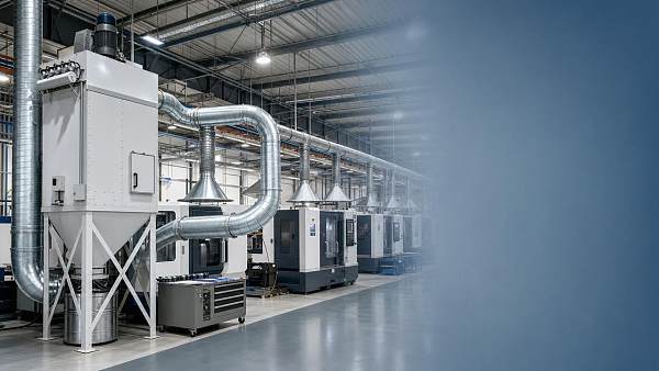
CFM means cubic feet per minute, but in dust collection it should be understood as usable airflow delivered where dust is generated. A collector rated at 4,000 CFM at free air does not deliver the same airflow once connected to 20–40 feet of duct, elbows, flex hose, a dirty filter, and a capture hood with poor geometry. That gap between rated airflow and effective airflow is where many sizing errors begin.
In real shop conditions, industrial dust collection CFM must be matched to three linked requirements: capture velocity at the source, conveying velocity in the duct, and collector capacity at the expected static pressure. If one of these three is missed, the system may either fail to capture fine dust or waste power by moving excess air where it is not needed.
The three airflow questions operators should ask
- How much air does each machine or hood need to capture dust at the point of generation?
- How much velocity is required to keep material suspended in the duct, often around 3,500–4,500 FPM for many dry dusts?
- What airflow will the collector still provide when static pressure reaches a realistic range such as 6–10 inches w.g.?
Why catalog CFM alone causes trouble
A common mistake is selecting a collector by machine count alone. For example, three machines labeled at 800 CFM each do not automatically require a 2,400 CFM collector. If only two run at once, the simultaneity factor may be 65%–80%. On the other hand, if duct losses are high or hoods are inefficient, even 2,400 CFM may be too low. The right answer depends on real use patterns, not nameplate totals.
This matters across the broader manufacturing landscape tracked by GIM, where fabrication cells often combine legacy equipment, new CNC lines, robotic trimming, and portable stations. Airflow planning must fit mixed operating behavior, not idealized design conditions.
Typical airflow demand by process type
The table below shows practical airflow ranges operators often use as a starting point. These are not universal design values, but they help frame industrial dust collection CFM requirements before a full duct and hood review.
These ranges show why industrial dust collection CFM must be process-specific. A manual dump station may need less total airflow than a router, yet still perform worse if hood placement is poor. Effective sizing starts with process behavior, not with collector horsepower alone.
How to Size Airflow for Real Shop Conditions
A reliable sizing workflow usually takes 5 steps. It begins at the source and works outward through the duct network, rather than starting with a collector model. For shops with 4–20 dust points, this approach reduces the risk of under-sizing branches or over-sizing the main trunk.
Step 1: List every dust-generating point
Create a machine and hood list with at least 6 fields: machine name, dust type, required pickup CFM, duct diameter, typical daily runtime, and whether it runs simultaneously with other stations. This simple sheet often reveals that only 50%–70% of all connected points operate at the same time.
Step 2: Define realistic simultaneous use
Do not assume all blast gates are open all day unless your process truly works that way. In many fabrication shops, one deburring line runs continuously, two sanding booths cycle every 10–15 minutes, and a cleanout station is used only 1–2 hours per shift. This operating pattern can change collector sizing by 20%–40%.
Step 3: Check transport velocity in each duct section
Once you estimate airflow, verify that duct velocity remains high enough to prevent settling. Many dry industrial dusts require roughly 3,500 FPM minimum, while heavier metal dust or mixed chips may need 4,000–4,500 FPM. If airflow is too low for the chosen duct diameter, the line may clog even when the collector fan is technically large enough.
Step 4: Estimate static pressure under loaded conditions
Static pressure should include branch losses, elbows, entry loss, hood loss, dust collector resistance, and filter loading. Designing only for clean filters can create weak capture after a few weeks. A more stable planning point is the expected operating range after normal dust cake develops, often several inches higher than the clean condition.
Step 5: Add sensible reserve, not oversized excess
A reserve factor of 10%–20% is often practical for future tool wear, moderate line extension, or process variation. Going far beyond that can increase energy use, noise, and filter velocity without improving capture. In many systems, oversizing by 35% or more creates balancing problems rather than operational resilience.
A simplified field formula
For preliminary planning, operators often use this sequence: sum the CFM of all simultaneously active pickups, adjust for actual hood effectiveness, then verify duct velocity and fan capacity at target static pressure. This is not a substitute for full engineering, but it gives a much better result than selecting by collector size category alone.
Factors That Change CFM Demand More Than Most Teams Expect
Two systems with the same nominal CFM can perform very differently because airflow demand is shaped by details on the floor. In mixed-sector production, these details may include mobile operators, variable machine doors, flexible duct sections, and product changeovers that happen 3–8 times per week.
Hood design and distance to dust source
An open hood located 12 inches from the dust source may require dramatically more airflow than a close-capture hood positioned 2–4 inches away. Every extra gap reduces capture efficiency. In practice, improving hood geometry can lower required industrial dust collection CFM more effectively than buying a larger fan.
Duct layout quality
Long runs, sharp elbows, reducers placed too close together, and excess flex hose all raise pressure loss. A system with 6 elbows and 25 feet of flex can behave much worse than a smoother design with 3 long-radius elbows and 8 feet of flex. That difference changes actual airflow available at the hood.
Material type and dust loading
Light paper-like dust, fibrous agri-residue, aluminum fines, and dense grinding particulate do not move the same way. Heavier or more abrasive material usually needs stronger conveying conditions and more frequent inspection. Dust loading rate also matters: a station generating short peaks of heavy dust may need higher capture airflow than one with low but continuous emissions.
Operator habits and gate management
If unused branches remain open, the collector may lose 15%–30% of effective airflow at the active machine. Shops should train operators on gate position, hood placement, and routine checks. In many cases, better daily use recovers performance without any capital upgrade.
The table below highlights common shop variables that alter industrial dust collection CFM and what action usually helps most.
The main lesson is that airflow demand is dynamic. When teams review industrial dust collection CFM through hood quality, duct resistance, dust behavior, and daily operating discipline, they usually identify practical improvements before replacing the whole collector.
Common Sizing Mistakes and How to Avoid Them
Many underperforming systems are not caused by poor hardware quality. They fail because the original sizing logic ignored one or two field realities. The following issues are especially common in facilities that expanded in phases over 2–5 years.
Mistake 1: Sizing by collector horsepower
A 10 HP collector is not automatically better for your process than a properly matched 7.5 HP unit. Fan curve, system pressure, and hood efficiency determine delivered performance. Always look at airflow at expected resistance, not motor size in isolation.
Mistake 2: Ignoring future dust point additions
If you expect to add 1–3 machines within the next 12–18 months, include a moderate reserve during planning. Retrofitting a main duct or fan later may cost more than allowing measured growth from the start. The key is measured capacity, not blind oversizing.
Mistake 3: Using one rule for all dust types
Fine polymer dust, agricultural dry matter, and steel grinding waste behave differently in both hoods and ducts. A one-size rule can lead to settling, abrasion, or poor source capture. Match your industrial dust collection CFM plan to the actual material stream.
Mistake 4: Forgetting maintenance effects
Dirty filters, leaking seals, and worn dampers gradually change system behavior. If inspections happen only once per quarter, performance may drift for weeks before anyone notices. A short weekly checklist can prevent the false assumption that the original CFM sizing was wrong.
A practical operator checklist
- Confirm which machines actually run together on each shift.
- Check that all inactive blast gates are closed.
- Inspect hood distance and guard openings after setup changes.
- Review filter differential pressure trend every week.
- Measure branch airflow or velocity at problem points every 30–90 days.
Using CFM Planning to Support Better Procurement and System Upgrades
For procurement teams and operators working together, industrial dust collection CFM should be part of a broader equipment decision. The best purchase is not always the largest collector, but the package that aligns airflow, duct design, maintenance access, control logic, and expected process growth.
What to request from a supplier or integrator
- A fan performance point tied to your estimated operating static pressure, not just free-air CFM
- A branch-by-branch airflow plan for simultaneously used machines
- A duct velocity review for heavy and fine dust sections
- A maintenance outline covering filters, cleaning cycles, and inspection frequency
- An allowance for 10%–20% future demand if your production plan supports it
Why cross-sector benchmarking matters
In modern manufacturing, one site may combine metal fabrication, electrical cabinet assembly, composite trimming, and utility module packaging. GIM’s cross-industry benchmarking approach is useful in such environments because airflow decisions affect energy use, housekeeping, uptime, and worker exposure across multiple process families. A dust collection decision is rarely isolated from the broader production system.
When industrial dust collection CFM is planned around actual workflow, the result is usually cleaner capture, lower dust accumulation on surfaces, fewer nuisance blockages, and more predictable maintenance intervals. Those outcomes matter to operators every shift and to decision-makers over the full life of the system.
Correct sizing starts with how your shop truly works: what runs together, how dust is generated, where hoods are placed, and how the duct system behaves after weeks of use. If you need a clearer basis for equipment selection, retrofit planning, or technical benchmarking across mixed manufacturing operations, GIM can help translate process conditions into a more practical airflow strategy. Contact us to discuss your application, request a tailored assessment, or explore more industrial solutions.

The Archive Newsletter
Critical industrial intelligence delivered every Tuesday. Peer-reviewed summaries of the week's most impactful logistics and market shifts.