Monday, May 22, 2024

How Do CNC Milling Machines Affect Part Tolerances?
by
Published
Views:
How Do CNC Milling Machines Affect Part Tolerances?
How do CNC milling machines affect part tolerance? The answer goes beyond a machine’s advertised accuracy. Axis positioning, spindle runout, thermal stability, tool wear, workholding, and cutting parameters all influence whether finished parts meet dimensional requirements. A milling machine establishes part of the precision envelope; the complete manufacturing process determines how much of that precision reaches the component.
That distinction matters when a bore must locate a bearing, a sealing face must remain flat, or mounting holes must align across an assembly. A supplier may produce one acceptable sample yet struggle to maintain the same result throughout a production run. Evaluating tolerances therefore means looking at repeatable process capability, not simply comparing machine specifications.
The Drawing Sets the Tolerance; the Process Must Hold It
Strictly speaking, a CNC milling machine does not change the specified tolerance. The drawing defines the permitted variation. The machine and machining process affect the actual dimensions and geometry, determining whether the finished part stays within those limits.
Three terms are worth separating. Accuracy describes how closely an achieved position or dimension agrees with its intended value. Repeatability describes how consistently the system returns to the same result. Resolution is the smallest increment the controller or feedback system can represent. Fine command resolution does not guarantee equally fine cutting accuracy.
Nor is dimensional size the whole requirement. A bore can meet its diameter limit while failing position or cylindricity requirements. A mounting surface can have an acceptable average height but unacceptable flatness. Surface roughness is another separate characteristic: a smooth finish does not prove that a feature is correctly sized or located.
Before discussing equipment, identify the functional characteristics that matter, their datum references, and how they will be measured. Otherwise, a quotation promising “tight tolerances” says very little.
Where Machine Errors Enter the Part
The machine’s mechanical structure and motion system establish a baseline. Positioning errors, backlash, axis straightness, squareness, and spindle alignment can all appear in the finished geometry. Their influence depends on where the feature sits in the working envelope and how the tool moves to create it.
For example, axis squareness errors can affect perpendicular faces and hole patterns. Reversal errors can become visible when interpolating a circular pocket. On a five-axis machine, rotary-axis positioning and alignment errors can influence features machined at different orientations, particularly when the tool tip is far from the rotary center.
Machine stiffness matters under cutting load. The spindle, toolholder, cutter, fixture, workpiece, and machine structure form a connected mechanical system. Deflection anywhere in that system can shift a wall, taper a pocket, or disturb flatness. A static positioning test does not fully describe this behavior.
Spindle and toolholder runout introduce another error source. Unequal cutting-edge engagement can affect feature size, finish, and wear. The resulting dimensional error is not necessarily equal to the measured runout; cutter geometry and engagement determine how it appears on the part.
This is why a machine’s inspection certificate should be treated as baseline evidence rather than a finished-part guarantee. The ISO 230 series addresses machine-tool testing, while the ISO 10791 series covers machining-center test conditions. Relevant results support benchmarking, but they cannot replace cutting trials on representative geometry.
Thermal Stability Often Decides Whether Precision Lasts
A machine that produces an acceptable first part may drift after sustained operation. Spindle heating, axis movement, coolant temperature, ambient conditions, and workpiece temperature can change the relative position of the tool and component.
Thermal compensation can reduce predictable errors, but it depends on suitable sensors, models, and operating conditions. It should not be assumed to correct every temperature-related disturbance. Warm-up routines and coolant management remain important, especially when production alternates between long idle periods and heavy cutting.
Inspection introduces its own temperature question. ISO 1 establishes 20°C as the standard reference temperature for geometrical and dimensional properties. That does not mean every measurement must occur in a room held at exactly that temperature, but temperature differences and compensation must be considered when they are significant relative to the tolerance.
A warm aluminum part measured immediately after machining may not have the same dimensions after stabilization. Without agreed inspection conditions, supplier and customer can disagree even when both instruments function correctly.
Tooling and Workholding Can Defeat an Accurate Machine
Long tool reach, thin walls, deep pockets, and weak clamping arrangements frequently create tolerance problems that cannot be solved through machine positioning alone. A slender end mill bends under load. A thin wall moves as material is removed. A component clamped flat can spring out of shape when released.
The important geometry is the geometry required in the specified inspection condition—not necessarily what exists while the part is forced against a fixture. When restrained inspection is necessary, that condition should be explicitly agreed rather than assumed.
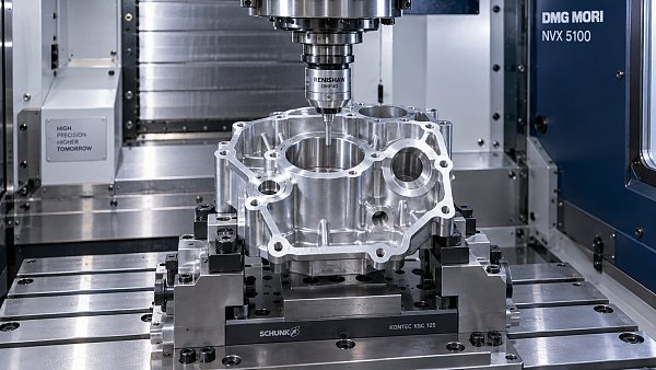
Tool wear also changes the process over time. Depending on the operation, wear can shift feature size, increase cutting forces, or degrade surface integrity. Scheduled tool changes and measured offset corrections help, but their effectiveness must be demonstrated across tool life. A successful cut with a new tool is not enough.
Material behavior complicates matters further. Removing stock can release residual stress and distort the component. Balanced roughing, suitable finishing allowances, and intermediate stabilization may be needed. These decisions depend on alloy, stock condition, and geometry; no single sequence suits every part.
Programming Choices Affect More Than Cycle Time
Feed rate, cutting speed, depth of cut, and tool engagement influence forces and heat. Raising productivity without considering those effects can move the process outside its dimensional window. Conversely, simply slowing everything down does not guarantee precision: unsuitable cutting conditions can encourage rubbing, built-up edge, or unstable cutting.
Separating roughing and finishing often helps because the finishing tool encounters a more consistent allowance. However, that allowance must suit the material and tool. An inconsistent stock envelope can cause variable deflection even when the programmed finishing path is identical.
For contoured surfaces, CAM approximation settings and controller smoothing also matter. Coarse path approximation or aggressive smoothing can produce departures from nominal geometry. Extremely fine toolpaths may increase processing demands without improving the result if mechanical or thermal errors already dominate.
Additional setups introduce another trade-off. Machining related features in one setup can reduce datum-transfer errors, which is a useful advantage of multi-axis equipment. But more axes are not automatically more accurate. The gain depends on calibration, fixture access, tool reach, and the geometry being controlled.
What Evidence Should a Supplier Provide?
There is no universal tolerance that every CNC milling machine can hold across all parts. Claims detached from feature size, material, geometry, and production conditions are poor purchasing criteria. A short, rigid component and a large thin-walled housing present very different challenges.
A useful supplier review follows the critical feature from drawing to inspection:
- Confirm the requirement: identify size limits, geometric tolerances, datum references, surface requirements, and any post-machining treatments.
- Review comparable capability: seek evidence involving similar materials, feature dimensions, tool reach, and setup complexity—not merely a photograph of a precision component.
- Check production variation: examine results across time, tool changes, setups, and relevant machines rather than relying only on an approved first article.
- Validate inspection: establish the measurement method, sampling plan, uncertainty, temperature conditions, and acceptance rules.
- Understand reaction plans: determine what happens when dimensions trend toward a limit, including offset adjustment, tool replacement, containment, and reinspection.
Capability indices such as Cp and Cpk can support this review, but only when the process is statistically stable and the data and measurement system are suitable. A reported index without context can hide drift, mixed production streams, or inadequate measurement resolution.
On-machine probing is useful for locating workpieces and controlling offsets. It is not automatically independent verification: machining and probing can share some machine-related errors. Critical features may still require an external measurement method with appropriate uncertainty.
Choose Precision Around Function, Not a Blanket Number
Applying the tightest available tolerance to every dimension usually adds cost without improving the assembly. Concentrate control on bearing interfaces, locating features, sealing surfaces, and other characteristics that affect function. Clearance features and nonfunctional surfaces may permit wider limits.
The final manufacturing route matters too. Heat treatment, coating, and other downstream operations can change dimensions or geometry. Some requirements may be better served by grinding, honing, or another finishing process after milling. Those operations should be considered during quotation, not after repeated rejection.
Cross-sector benchmarking makes these distinctions clearer. An electronics fixture, an automotive housing, an agricultural actuator component, and an environmental filtration assembly can all require precision milling, but their functional risks and qualification requirements differ.
Global Industrial Matrix (GIM) approaches this through its multidisciplinary technical benchmarking framework, connecting precision tooling with electronics, mobility, smart agriculture, and industrial infrastructure. The useful comparison is between verified requirements, manufacturing methods, and inspection evidence. ISO, IATF, and IPC references must be selected for their actual scope; they are not interchangeable guarantees of milling accuracy.
Before committing to production, agree on the critical characteristics and request a representative trial with an inspection plan. The decisive question is not how precisely the machine can move under ideal conditions. It is whether the complete process can repeatedly deliver the required geometry after unclamping, stabilization, and any specified downstream operations.

The Archive Newsletter
Critical industrial intelligence delivered every Tuesday. Peer-reviewed summaries of the week's most impactful logistics and market shifts.