Monday, May 22, 2024

How supporting technology information improves CNC process planning
by
Published
Views:
A CNC plan can look complete on paper and still fail at the machine. The drawing may define geometry, tolerances, and material, yet the programmer may not know whether the stock arrives stress-relieved, whether a specified coating requires a particular tool edge condition, whether the fixture datum reflects the inspection datum, or whether a downstream assembly treats a surface differently from a cosmetic face. These gaps often surface as excessive prove-out time, unstable cycle times, unexpected tool wear, or inspection disputes.
The practical answer is that supporting technology information for manufacturing improves CNC process planning by turning a drawing into a controlled manufacturing decision set. It gives planners the context to select machining methods, tooling, workholding, inspection routes, automation interfaces, and supplier assumptions before production starts. The drawing remains the authority for part requirements, but supporting information explains how those requirements can be achieved repeatedly under real production conditions.
The drawing is necessary, but it does not define the whole process
Part drawings are designed to communicate required features. CNC process planning must also account for the behavior of the material, machine, tools, fixtures, measurement system, and production flow. A nominal dimension alone does not reveal whether a thin-wall feature will move after roughing, whether a bore must be finished in the same clamping as a mating face, or whether a surface callout has functional implications for sealing, adhesion, conductivity, or fatigue performance.
This distinction matters most when technical evaluators compare a machining capability against a demanding component family. Two suppliers may both have suitable machine travels and spindle ratings. Their real difference may lie in the supporting information available to their planners: controlled material certificates, tool-life records, fixture validation notes, prior process capability evidence, inspection instructions, and documented interfaces with heat treatment, plating, cleaning, or assembly.
Without that information, planners tend to fill the gaps with assumptions. Assumptions may be harmless on an open-tolerance bracket, but they become risky on precision housings, thermal-management components, safety-relevant mobility parts, semiconductor equipment structures, agricultural drivetrain parts, or corrosion-exposed infrastructure hardware.
Start by separating feature requirements from process conditions
A useful review begins by asking two different questions for every critical feature: what must the finished part be? and what conditions must be controlled to make it that way? The first question comes primarily from the drawing and specification. The second relies on supporting technology information.
This separation prevents a common planning error: treating every dimension as an isolated machining task. In production, features interact. A bore position may depend on the face used to locate the part. That face may distort during clamping. The clamping force may need adjustment because the stock is thin, cast, welded, or has uneven hardness. Supporting data makes those links visible early enough to influence the route.
Material information changes more than feeds and speeds
Material callouts are often read too narrowly. Knowing that a part is stainless steel, aluminum, alloy steel, polymer composite, or cast iron is not enough for robust planning. The relevant questions include the exact grade, delivery condition, hardness range, heat-treatment state, stock form, internal discontinuity controls where applicable, and expected variation between batches.
For example, a planner dealing with an aluminum component may need to distinguish between plate, extrusion, forged stock, and casting. The nominal alloy may be similar, while machinability, porosity risk, distortion behavior, and clamp response are materially different. A steel component may require confirmation of whether heat treatment occurs before or after machining, because that choice affects stock allowance, tool wear, dimensional movement, and the finishing sequence.
Material information also supports a more realistic tool strategy. Tool selection is not simply a catalog exercise. The process must consider flute geometry, substrate, coating, runout sensitivity, corner treatment, coolant delivery, and expected engagement. When the material condition is uncertain, an aggressive cycle-time target can lead to inconsistent chips, built-up edge, rapid wear, or poor surface integrity. Planners should mark such uncertainty as a decision gate rather than bury it in a generic setup note.
Use tolerance data to design the sequence, not just the inspection plan
Tight tolerances are frequently interpreted as an inspection challenge after machining. In reality, they should shape the process sequence before the first operation is programmed. Critical positional, flatness, roundness, profile, and surface-finish requirements need to be traced back to their functional datums and the operations that establish those datums.
Consider a component with a precision bore, a sealing face, and a patterned hole group. If the bore and sealing face govern assembly alignment, finishing them in unrelated setups can create avoidable stack-up. A better route may establish the functional face, finish the bore while the part remains referenced to that face, and machine the hole group from the same datum structure or a validated transfer arrangement. The precise route depends on part geometry, but the decision should be explicit.
Supporting documents that clarify datum interpretation, mating-part relationships, allowable burr condition, and surface-function requirements are especially valuable here. A note such as “remove burrs” is not sufficient when a burr can affect a seal, bearing seat, electrical interface, or automated assembly. The planner needs a defined edge condition, an accessible deburring method, and an inspection approach proportionate to the feature risk.
Questions that should be resolved before programming
- Which drawing datums are functional assembly references, and which are convenient inspection references?
- Does a tolerance apply in the free state, clamped state, or after a later process such as coating or heat treatment?
- Are there surfaces that cannot be marked, clamped, contacted, or exposed to certain coolants?
- Do cosmetic surfaces have a defined appearance standard, or only a roughness requirement?
- Is there a required machining allowance for surfaces that will be ground, coated, lapped, or otherwise finished later?
These are not administrative details. Each answer can alter fixture design, operation order, stock allowance, probing strategy, or the choice between milling, drilling, reaming, boring, grinding, or another finishing method.
Workholding data is often the missing link between a good program and a stable process
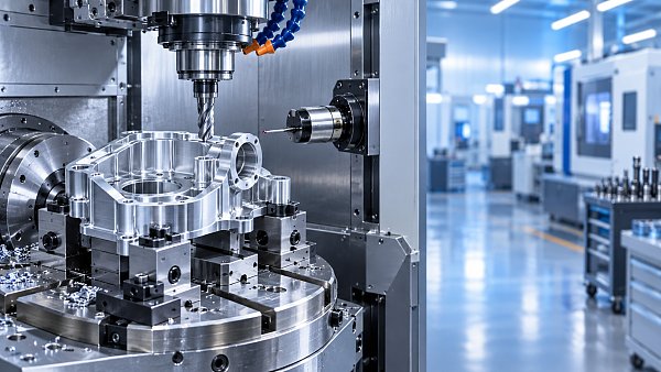
A CAM simulation can confirm cutter reach and collision avoidance, but it does not prove that the part will remain stable under cutting load. Workholding must control location, support, clamp force, part deformation, chip access, and repeatability between cycles. Information about raw-part variation is therefore as important as the nominal CAD model.
Cast, forged, welded, molded, and additive near-net shapes deserve particular attention. Their locating surfaces may vary, their walls may not be uniform, and their residual stresses may be different from a machined billet. A fixture planned from ideal geometry can produce unreliable datum pickup or excessive stock variation. The routing should identify whether an initial cleaning, scanning, roughing, or datum-creation operation is needed before precision machining begins.
For components intended for palletized or robotic handling, fixture information must extend beyond clamping. The planner should check pallet interface accuracy, orientation control, gripper clearance, part-present confirmation, chip accumulation zones, and whether probing can distinguish a correctly seated part from one resting on trapped chips. Automation is not simply an add-on to a manual setup; it requires process information that makes abnormal conditions detectable.
Bring adjacent processes into the CNC planning review
CNC machining is rarely the only operation that influences final conformance. Heat treatment can move dimensions. Plating and anodizing can affect threaded fits and surface conditions. Welding can introduce distortion. Cleaning may be required before inspection or assembly. Packaging may need to prevent damage to precision edges or protected surfaces. When these steps are treated as external events rather than process inputs, the machining plan becomes incomplete.
The most effective approach is to map each critical feature against its full route. A threaded hole, for instance, may need masking before coating, a post-coat gauge check, and defined handling to avoid thread damage. A sealing face may need protection after final machining and may not tolerate a later abrasive cleaning operation. A precision-machined casting may need to be inspected for porosity exposure after roughing, not only after all finishing time has been spent.
Cross-sector benchmarks are useful when they are applied to the actual technical question. Relevant standards, customer specifications, and internal process controls can help define terminology, traceability expectations, measurement methods, and material documentation. They should not be used as a substitute for reviewing the specific part requirement. A standard can frame the control method; the drawing and product specification still determine acceptance.
Build an information pack that planners can actually use
More documentation does not automatically create a better process. The useful information must be current, attributable, and available at the moment decisions are made. A planning pack should distinguish controlled requirements from background reference material and should identify unresolved items clearly.
- Freeze the technical baseline. Collect the latest drawing, 3D model where available, revision history, material specification, and applicable customer requirements. Confirm that model and drawing do not conflict.
- Flag critical characteristics. Identify dimensions or surfaces that affect fit, sealing, motion, safety, thermal performance, electrical function, or downstream automation. Give each one a proposed datum and verification route.
- Capture raw-material reality. Record stock form, condition, permitted variation, supplier documentation, prior-process state, and any known machining sensitivities.
- Define the manufacturing route. Establish datum creation, roughing, stress-management steps where required, semi-finishing, finishing, deburring, cleaning, and handoff points to adjacent processes.
- Link tooling and workholding assumptions. Document tool access, minimum clamp support, likely chip paths, probe locations, tool-life control method, and recovery steps after a tool change or interrupted cycle.
- Match inspection to the route. Specify in-process checks for features that cannot be economically recovered later. Ensure final inspection uses the intended functional datum relationship.
This pack should be revised when the material source, machine platform, fixture concept, or post-machining route changes. Reusing an old process plan without reviewing these assumptions is a frequent cause of slow launches. A proven program can still be unsuitable when moved to a different machine, batch condition, fixture, or supply chain.
Evaluate information quality, not just information availability
Technical evaluators should ask whether a document supports a decision or merely describes a requirement. A material certificate may confirm a grade, yet not answer whether the delivered hardness range is compatible with the selected cutter. A machine capability statement may list accuracy, yet not describe thermal management, probing use, or the fixture conditions under which repeatability is maintained. An inspection report may show a compliant sample, yet not reveal the datum setup or measurement uncertainty relevant to the feature.
Useful supporting information is specific enough to influence an action. It states the revision, source, applicability, and limitations. It makes process assumptions visible: which surfaces locate the part, when stock is removed, how a critical bore is finished, what happens after tool-life limits are reached, and which downstream process may alter the result. This level of traceability reduces ambiguity during technical review and makes later root-cause work faster when variation appears.
When a process cannot be finalized because a functional requirement is unclear, the right response is not to invent a default. Hold the affected decision, identify the missing input, and assess the risk of proceeding. That discipline is especially important for requirements involving safety, regulated performance, critical sealing, precision fit, or compatibility with automated assembly and inspection.
Well-managed supporting technology information does not replace skilled CNC programming. It gives programming, tooling, fixture design, quality control, and supply-chain planning the same factual basis. The result is a process plan that is easier to review, more defensible when conditions change, and less dependent on discovering essential constraints during production.
The Archive Newsletter
Critical industrial intelligence delivered every Tuesday. Peer-reviewed summaries of the week's most impactful logistics and market shifts.