
The maintenance that most reliably reduces CNC milling machine downtime combines consistent lubrication, coolant control, chip removal, and inspections of spindles, toolholders, and machine accuracy.
For production managers and maintenance engineers, the priority is preventing recurring stoppages while detecting developing faults early enough to schedule repairs around production commitments.
Manufacturer service instructions establish the baseline. Operating hours, workpiece materials, contamination, machine condition, and failure history determine where that baseline needs additional attention or shorter intervals.
Drawing on Global Industrial Matrix’s cross-sector benchmarking perspective, this guide explains how to prioritize maintenance, recognize warning signs, and build a schedule that protects availability.
Which Maintenance Tasks Should You Prioritize First?
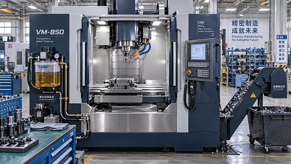
Start with the failures already interrupting your operation. A machine repeatedly stopping for lubrication alarms needs a different maintenance emphasis than one suffering tool-change faults.
Review recent downtime records and group incidents by cause: lubrication, coolant, chips, tooling, spindle, axes, controls, utilities, or unresolved faults requiring further investigation and diagnosis.
Rank these causes by lost production hours, recurrence, repair expense, and consequences for part quality. Frequency alone can obscure occasional failures with much larger operational effects.
Daily attention should usually concentrate on fluid delivery, contamination control, tool interfaces, and visible abnormalities. These checks expose problems before damaged components require lengthy repairs.
Separate operator inspections from specialist maintenance. Operators can identify leaks and abnormal sounds; trained technicians should investigate internal spindle faults, electrical problems, and alignment corrections.
Perform cleaning and inspection under the machine manufacturer’s procedures. Where servicing exposes someone to hazardous motion or energy, apply the site’s required isolation and lockout procedures.
The practical objective is a short, repeatable routine with clear escalation criteria. A long checklist provides little protection when production pressure causes important checks to disappear.
Keep Lubrication Reaching the Components That Need It
Checking reservoir level is necessary, but it does not prove lubricant reaches every guideway or ball screw. Delivery failures can occur despite a full reservoir.
Inspect accessible lines for damage and leakage, confirm applicable lubrication alarms function, and verify delivery using the manufacturer’s approved method for that machine’s lubrication system.
Blocked metering devices, broken tubing, air ingress, or pump faults can starve individual lubrication points. Investigate recurring alarms instead of repeatedly clearing them and continuing production.
Use the specified lubricant grade and approved product compatibility. Substituting an apparently similar oil can affect pump operation, distribution, seals, or lubrication performance under load.
Watch for changes in axis noise, movement smoothness, servo load, and positioning repeatability. These symptoms warrant investigation because lubrication loss is only one possible cause.
Clean accessible way covers and inspect their condition. Damaged covers or wipers allow chips and coolant into areas where contamination can accelerate mechanical wear substantially.
If lubrication delivery fails, follow the manufacturer’s stop and recovery instructions. Continuing to machine through a lubrication fault can turn a service issue into component damage.
Record lubricant consumption alongside operating hours. Unexpected increases may indicate leakage; unusually low consumption may indicate failed delivery, depending on the system’s design and operating conditions.
Control Coolant and Chips Before They Interrupt Production
Coolant problems cause downtime through blocked flow, pump trouble, contamination, and unstable machining conditions. Their effects often appear first as deteriorating tool life or surface finish.
Measure concentration with a suitable refractometer and apply the coolant supplier’s correction factor. Compare results with the recommended range for the material and machining operation.
A refractometer reading alone does not establish coolant health. Follow supplier guidance for additional checks, which may include pH, microbial condition, water quality, and tramp oil.
Check coolant level, nozzle position, strainers, filters, and accessible hoses. Restricted delivery can compromise chip evacuation even when the sump contains enough fluid for operation.
For through-spindle coolant systems, maintain filtration and verify pressure or flow against machine requirements. Repeated low-pressure alarms deserve diagnosis rather than repeated resets during production.
Remove accumulated chips from approved areas and inspect conveyor operation. Bridging, jams, and overloaded bins can stop unattended machining even when the cutting process remains stable.
Use manufacturer-approved cleaning methods around seals, way covers, and electrical equipment. Avoid directing compressed air where it can force contamination into protected mechanisms or sensitive components.
Track filter service and coolant changes by condition and usage. A machine cutting abrasive materials or producing heavy chip loads may need more frequent attention.
Inspect Toolholders and Spindles Without Creating New Problems
Dirty or damaged tool interfaces can contribute to runout, poor finish, vibration, and unreliable tool retention. Routine cleaning is relatively inexpensive compared with spindle repair.
Inspect toolholder tapers, contact surfaces, pull studs where fitted, and spindle interfaces according to manufacturer instructions. Remove damaged holders from service and investigate unusual wear patterns.
Confirm pull studs match the specified geometry and installation requirements. Incorrect components or assembly practices can compromise clamping even when a holder appears acceptable externally.
Check tool clamping force at the recommended interval using appropriate equipment and qualified personnel. A declining result requires diagnosis of the retention system before continued use.
Trend spindle vibration and temperature under repeatable conditions. Comparing different speeds, tools, loads, or warm-up states can produce misleading conclusions about the machine’s mechanical condition.
Follow the prescribed spindle warm-up cycle after relevant idle periods. Warm-up requirements differ by spindle design, lubrication system, ambient conditions, and the accuracy needed for production.
After a collision, stop and assess the machine under an approved recovery procedure. Check affected tooling, spindle condition, positioning, and alignment before releasing production again.
Tool changers also deserve inspection of accessible pockets, grippers, sensors, and debris buildup. Repeated change failures often justify targeted servicing before an unattended shift begins.
Build a Maintenance Schedule Around Usage and Failure Risk
A useful schedule identifies the task, responsible person, interval, acceptance criteria, and action required when results fall outside limits. “Inspect machine” is too vague to execute.
The following framework illustrates how to organize work. Confirm every task and interval against the machine manual, installed options, operating conditions, and your maintenance history.
Schedule hour-based tasks by actual machine use where appropriate. Calendar-only scheduling can underservice heavily utilized equipment while consuming unnecessary effort on lightly used machines elsewhere.
Assign operators the checks they can perform consistently and safely. Give maintenance technicians defined ownership of diagnosis, specialist measurements, corrective work, and records of completed service.
Place planned service windows alongside production scheduling. Maintenance that requires a technician, spare parts, or machine access should not depend on an unexpected gap appearing.
Close each work order with findings and verification results. A completed checkbox without evidence of restored function makes recurring problems harder to understand and prevent.
Use Condition Monitoring Where It Changes Maintenance Decisions
Condition monitoring is valuable when a measurement leads to a clear action. Begin with components whose failure would stop a bottleneck machine or disrupt delivery.
Useful signals can include spindle vibration, temperature, axis load, lubrication pressure, coolant flow, and alarm frequency. Available signals depend on the machine and installed systems.
Establish baselines during known healthy operation and document operating conditions. Evaluate comparable readings over time instead of treating every deviation as evidence of imminent failure.
Use manufacturer limits where available and define site escalation thresholds with qualified specialists. Generic vibration or temperature limits may be inappropriate for a particular spindle.
When a trend worsens, combine the data with inspection and process context. Tool imbalance, changed cutting conditions, ambient temperature, and sensor problems can influence measurements.
Geometric checks, ballbar testing, or positioning assessments can help investigate accuracy drift when appropriate. Choose the test to answer a specific question about machine performance.
Monitoring supplements routine care. It cannot compensate for neglected lubrication, contaminated coolant, or unaddressed alarms, and additional sensors only help when someone owns the response.
Measure the Business Benefit and Prepare for Necessary Repairs
Track unplanned downtime hours, failure frequency, repair duration, and maintenance-related quality losses. Together, these measures show whether the maintenance program improves production reliability in practice.
Distinguish planned maintenance time from breakdown time. A short scheduled service may improve delivery performance even if the machine’s total recorded maintenance hours increase initially.
Estimate downtime cost using relevant losses, including idle labor, disrupted output, overtime, scrap, and expedited shipments. Avoid counting the same production loss in multiple categories.
Compare the expected avoided loss with labor, consumables, service, and monitoring costs. Use your plant’s evidence rather than assuming a universal percentage reduction in downtime.
Stock critical spares according to failure consequences, supplier lead times, and compatibility. Filters, approved sensors, pumps, and selected tool-change components may justify local inventory where warranted.
Maintain current backups of programs, parameters, and control data according to manufacturer procedures. Confirm the recovery method before a control fault makes those backups urgently necessary.
GIM’s benchmarking perspective supports comparing maintenance results across machines using consistent definitions. Account for machine age, utilization, materials, and production mix before drawing conclusions about performance.
Make the Next Maintenance Decision Specific
What maintenance reduces CNC milling machine downtime? Prioritize reliable lubrication delivery, controlled coolant, effective chip evacuation, sound tool interfaces, and early investigation of abnormal machine behavior.
Start with your largest recurring downtime cause, assign ownership, and define a measurable inspection or corrective task. Then verify whether stoppages and repair time decline.
A strong program combines repeatable daily care with manufacturer-directed servicing and selective condition monitoring. Its value appears in reliable production, stable accuracy, and fewer emergency repairs.