Monday, May 22, 2024

Protecting precision agriculture electronics from fertilizer corrosion
by
Published
Views:
Protecting precision agriculture electronics from fertilizer corrosion starts with controlling where fertilizer residues collect, how moisture reaches them, and which electrical surfaces remain exposed. A sealed enclosure can reduce direct contamination, but long-term reliability also depends on cable entries, connector interfaces, circuit-board cleanliness, protective coatings, and maintenance access. The protection strategy should follow the equipment’s actual exposure: a controller beside a liquid fertilizer manifold faces different conditions from a guidance display inside a cab.
For engineering project leaders, the practical goal is to prevent contamination from creating electrical faults throughout the intended service life. That requires a coordinated design and qualification plan. Adding a coating late in development may leave vulnerable connectors or board edges untouched; specifying a high ingress-protection rating may overlook chemical compatibility or condensation. Both measures can help, provided their limits are understood and tested against the application.
Define the exposure before choosing the protection
“Fertilizer exposure” is too broad to serve as a design requirement. Dry granules, airborne dust, concentrated liquid fertilizer, diluted spray, and contaminated wash water create different challenges. Their effects depend on formulation, concentration, temperature, contact time, and the materials they reach. A compatibility claim for one fertilizer should not be extended automatically to another.
Dry residues can become electrically significant when moisture dissolves their soluble components. The resulting liquid can carry ions across exposed conductors, increasing leakage current and supporting corrosion. Under electrical bias, suitable combinations of contamination and moisture can also promote electrochemical migration, potentially forming conductive paths between closely spaced features. A device may therefore develop unstable readings or intermittent communication faults before visible corrosion becomes extensive.
Some deposits retain or attract moisture, prolonging surface wetness after the surrounding equipment appears dry. Repeated wetting and drying can redistribute contamination into seams and concentrate dissolved salts as water evaporates. Fertilizer trapped behind a connector seal, beneath a component, or inside a cable termination can consequently be harder to remove than an obvious spill on an enclosure.
Map exposure at the installed location, including servicing and cleaning. Useful distinctions include:
- Direct contact: leakage from pumps, hoses, valves, injection points, or tank fittings.
- Deposited contamination: dust or spray settling on connectors, enclosure joints, and cable surfaces.
- Moisture cycling: condensation, rain, irrigation, or wash water repeatedly wetting existing deposits.
- Service exposure: uncoupled connectors, open housings, and replacement parts handled with contaminated gloves or tools.
Include cleaning chemicals in this assessment. A housing material or seal that tolerates the fertilizer may respond differently to the detergent used to remove it. Likewise, a component protected during operation may be exposed during pressure washing or winter storage.
This exposure map establishes where additional protection earns its cost. Moving an electronic module away from a likely leak path, orienting a connector to shed liquid, or making a contaminated surface accessible for cleaning can reduce the burden on seals and coatings.
Protect the complete assembly, including its interfaces
Enclosure selection should combine ingress resistance with chemical compatibility and installation geometry. An ingress-protection rating describes performance under specified water and solid-particle tests; it does not establish resistance to a particular fertilizer formulation. It also does not establish performance after seals have aged, fasteners have loosened, or a cable has been pulled sideways repeatedly.
Review the enclosure, gasket, cable gland, connector body, adhesives, and exposed metal hardware as a system. Material names alone are insufficient. Elastomer behavior depends on the specific compound and exposure conditions, while plastics may be affected by temperature, mechanical stress, and chemical contact together. Request compatibility evidence for the relevant formulation or test representative materials where that evidence is missing.
Pay particular attention to joints that hold deposits. Recessed fasteners, upward-facing sockets, narrow ledges, and poorly drained mounting arrangements can retain contaminated liquid. An assembly that sheds spray on a bench may collect it when installed at a different angle on a tractor or implement. Drawings and qualification fixtures should reflect the intended mounting position and cable routing.
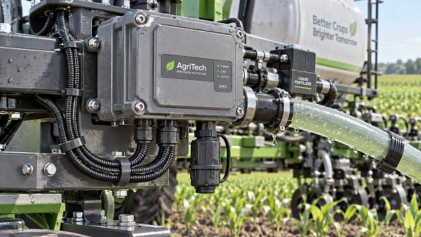
Connectors deserve separate scrutiny because they combine conductive contacts, mechanical movement, seals, and repeated handling. Evaluate protection in both mated and unmated states. A sealed connector may depend on the correct mating half, cavity plugs, cable diameter, crimp quality, and complete latch engagement. Unused ports and disconnected harness ends need suitable protection during storage and servicing.
Contact plating should be selected for the connector’s electrical duty and environment. Low-level sensor signals can be disrupted by contact degradation that would be less apparent in a power connection. Plating thickness, porosity, mating wear, and the underlying contact material all influence performance; a description such as “gold-plated” provides too little information to predict service life.
Cable assemblies can introduce additional entry paths. Liquid may travel along damaged jackets, poorly sealed terminations, or internal cable spaces. Strain relief and routing matter because movement can damage a seal without visibly breaking the connector. Qualification should therefore include the production harness, its support points, and the expected bending or vibration.
Pressure changes inside an enclosure can encourage moisture movement through imperfect seals. A suitable vent may help manage pressure differences, but its placement and resistance to fouling need review. Fertilizer deposits can affect vent performance. Venting also cannot guarantee that internal surfaces remain above the dew point, so condensation must be considered independently.
Use board protection where it can remain effective
Conformal coating provides a secondary barrier when moisture or contamination reaches the circuit board. Its effectiveness depends on the coating chemistry, substrate cleanliness, coverage, adhesion, and curing process. Selecting a coating from a material data sheet is only the beginning of specifying a reliable coated assembly.
Cleanliness comes first. Flux residues and other ionic contamination can create problems if left beneath a protective layer. A coating should not be treated as a remedy for an uncontrolled assembly-cleaning process. Define how boards are cleaned or otherwise demonstrated to be suitable for coating, how cleanliness is verified, and how handling prevents contamination from being reintroduced.
Coverage is especially important around component leads, sharp edges, closely spaced conductors, and areas shadowed by tall components. Connectors, switches, test points, and adjustable components may require masking, creating boundaries where protection ends. These boundaries should be reviewed against the exposure map. A coated board with an exposed, contamination-prone connector termination can retain a critical failure path.
Different coating families offer different balances of moisture resistance, chemical resistance, flexibility, processing requirements, and repairability. The appropriate choice depends on the assembly and its service model. A coating that performs well on a flat test coupon may crack, lift, or leave thin coverage on a populated board subjected to thermal cycling and vibration.
For supplier evaluation, ask for evidence that connects the selected material to the production process:
- Defined coverage areas, masking boundaries, and acceptable coating defects.
- Application and cure controls appropriate to the coating and board geometry.
- Inspection methods that can identify missed areas, bubbles, and adhesion problems.
- Documented rework procedures that restore protection after component replacement.
Potting or encapsulation may be appropriate for modules with sustained exposure and limited repair requirements. It introduces additional design constraints, including heat dissipation, cure behavior, mechanical stress, and access for failure analysis. Voids or weak interfaces can remain vulnerable, while incompatible materials can affect components or seals. Validate the encapsulated assembly under its electrical load and temperature range.
Sensors require a further distinction between protecting electronics and preserving measurement access. A humidity sensor, pressure interface, optical window, or electrochemical sensing surface may need contact with the environment. Applying a general-purpose barrier across that interface can change response time, calibration, or sensitivity. Protect the vulnerable electronics while qualifying the exposed sensing element for its intended contact conditions.
Qualify against the contamination cycle that causes failure
A useful qualification program reproduces the path from fertilizer exposure to electrical malfunction. Begin with a defined service profile: relevant formulations, representative concentrations, likely deposition or splash events, moisture cycles, operating temperatures, electrical duty, cleaning practices, and maintenance intervals. These inputs make test results interpretable and prevent a generic laboratory exposure from becoming a misleading durability claim.
Generic salt-spray testing may provide information about certain exposed materials, but it cannot by itself predict resistance to fertilizer service. Fertilizer solutions can differ in composition, pH, residue behavior, and interaction with protective materials. Use tests that address the identified failure mechanisms, alongside any applicable environmental or product requirements.
Test complete production-representative assemblies wherever practical. Include connectors, cable glands, vents, mounting hardware, harnesses, and the final coating or encapsulation process. Material coupons are useful for screening compatibility, but they cannot demonstrate that a finished enclosure joint or connector termination remains protected.
The sequence of exposure matters. For example, contamination followed by drying and humid conditions can reveal a different weakness from continuous immersion. Mechanical or thermal conditioning before chemical exposure may reveal seals or coatings that deteriorate with use. Choose the sequence to reflect credible service conditions, and avoid combining stresses so aggressively that the test creates an irrelevant failure mechanism.
Electrical operation should form part of the assessment where it influences failure. Bias can affect electrochemical processes, and intermittent faults may disappear when a unit is dried before inspection. Monitoring during exposure can reveal leakage, signal drift, communication errors, or abnormal current consumption that a final visual examination misses.
Agree on acceptance criteria before testing. Depending on the function, these may address sensor accuracy, insulation performance, contact resistance, communication stability, power consumption, and the condition of seals or coatings. Inspect internal surfaces after exposure even when the device still operates. Evidence of ingress or protective-layer damage can indicate limited reliability margin.
Accelerated testing supports comparison and identifies weaknesses, but translating exposure hours into field service years requires a defensible relationship between the test and the actual failure mechanism. For deployment decisions, combine qualification with a controlled field introduction and a practical way to capture early faults. Failed units should be preserved for analysis before cleaning removes useful evidence.
Make cleaning and service part of the design requirement
Protection can be lost during routine maintenance. Specify cleaning methods that remove fertilizer deposits without forcing liquid into interfaces or damaging protective materials. Define which connectors must remain mated or capped, whether power must be disconnected, which cleaning agents are compatible, and what drying or inspection is required before returning equipment to service.
Avoid prescribing rinse or pressure-wash procedures without checking the assembly design. Cleaning that is suitable for a metal frame may be unsuitable for a sensor port, vent membrane, or connector seal. Provide access to the areas where deposits are expected to accumulate; inaccessible contamination creates a maintenance problem that written instructions cannot solve.
For project release, the protection requirement should describe the expected exposure and the evidence needed to accept the assembly. “Sealed and conformally coated” is too vague. A useful specification links installation location, chemical contact, environmental cycling, connector states, cleaning methods, and functional acceptance criteria to the delivered hardware.
That level of definition also makes later changes easier to judge. A different gasket compound, coating process, connector supplier, or fertilizer formulation may alter the protection margin. Keeping those changes connected to the original exposure assumptions gives engineering teams a clear basis for deciding when compatibility review or repeat qualification is necessary.

The Archive Newsletter
Critical industrial intelligence delivered every Tuesday. Peer-reviewed summaries of the week's most impactful logistics and market shifts.