Monday, May 22, 2024

How mounting position affects ADAS LiDAR blind spots
by
Published
Views:
Mounting position determines which parts of the road an ADAS LiDAR can observe, even when its range and angular specifications appear sufficient. A roof installation can improve visibility over nearby vehicles while leaving a gap close to the host vehicle. A grille or bumper installation can bring the road surface into view sooner, but bodywork, traffic, and contamination can interrupt that advantage. Corner sensors can cover turning paths and lateral approaches, provided their fields of view overlap where the driving function needs them.
No mounting position eliminates every blind spot. For technical evaluation, the useful question is whether the installed sensor provides dependable observations of relevant objects early enough for the intended maneuver. That requires assessing height, orientation, surrounding bodywork, and detection performance together. A sensor’s advertised field of view describes its angular reach; it does not establish usable coverage on a finished vehicle.
How installation geometry creates a blind spot
Three different limitations are often grouped under “blind spots.” A geometric gap lies outside the sensor’s viewing angles. An occluded region sits within those angles but behind an obstruction. A detection gap occurs where the sensor has a clear line of sight yet produces insufficient information for the perception system to recognize or track the target. Mounting position influences all three, but each requires a different remedy.
Consider the lower edge of the vertical field of view. On level ground, if the lowest usable beam points downward by an angle θ from horizontal and the sensor is mounted at height h, that beam meets the road approximately at a horizontal distance of h / tan(θ). This simplified relationship assumes an unobstructed optical path, a flat road, and a beam that actually provides usable measurements at that angle.
For an illustrative calculation, a sensor mounted 1.5 meters above the road with a lowest beam directed 10 degrees downward intersects the ground about 8.5 meters ahead. At a mounting height of 0.6 meters, the equivalent intersection is about 3.4 meters. These are geometric examples, not detection specifications. They show why raising a sensor without changing its downward angular coverage can enlarge the close-range road-surface gap.
That ground intersection does not define the detection distance for every object. A pedestrian’s torso may intersect a beam while the feet remain outside coverage. A low object may fall entirely below the lowest beam. Evaluators therefore need separate visibility assessments for the target heights and shapes relevant to the driving function.
Tilting the sensor downward can reduce the near-field gap, but it also shifts the upper boundary of coverage downward. Depending on the vertical field of view and beam distribution, this can reduce observations of distant targets, rising roads, or objects above the sensor. Pitch should be evaluated across the complete operating scene rather than adjusted solely to make a stationary near-field diagram look better.
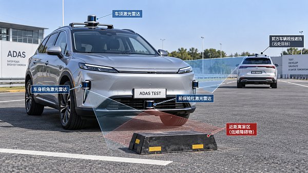
Vehicle attitude changes the geometry again. Braking, acceleration, suspension movement, and load variation alter the sensor’s position or orientation relative to the road. Road transitions matter as well: a crest can conceal the descending surface beyond it, while a dip or ramp changes where beams intersect the ground. A coverage assessment made with an unloaded vehicle on a level workshop floor captures only one installation condition.
Roof, grille, bumper, and corner positions expose different weaknesses
Roof mounting: a higher viewpoint with a near-field cost
A roof-mounted sensor can gain useful lines of sight over some nearby obstructions. Whether that helps depends on the relative heights of the sensor, intervening object, and target. An elevated viewpoint cannot see through a tall vehicle, and a target immediately behind an obstruction may remain hidden.
The main installation concern is the area close to the host vehicle. The roof, windshield surround, hood, or other structures may block downward rays before they reach the road. Moving the sensor forward can improve some sightlines, but the effect must be checked against the actual body shape. A wide vertical field of view has little value where the vehicle itself masks its lower portion.
Roof placement can therefore support forward observation while still requiring complementary sensing for low obstacles and close maneuvering. The distinction matters when comparing sensors for highway assistance with sensors expected to support parking, pulling away, or low-speed turning. Coverage adequate for one function may leave a consequential gap for another.
Grille and bumper mounting: closer to the road, more dependent on the opening
A lower forward position can improve geometric access to low targets and nearby road surfaces, assuming suitable downward coverage and minimum sensing range. It also puts the sensor at a height where intervening vehicles and roadside objects can readily block its view. A forward sensor with broad angular coverage may still lose sight of a cyclist approaching from the side behind another vehicle.
The mounting aperture deserves as much attention as the sensor specification. Grille bars, bumper edges, brackets, and decorative trim can clip the horizontal or vertical field of view. A recessed sensor may have a clear central view but lose oblique rays at the sides. Small changes to recess depth or opening dimensions can therefore affect the coverage needed during turns.
Any protective window adds another optical interface. Its material, angle, coatings, and condition can affect transmission and unwanted reflections. An opening that looks unobstructed in a mechanical drawing does not establish optical performance. Validation should use the intended fascia and window, including relevant manufacturing tolerances.
Lower installations also need an exposure assessment for road spray, mud, snow, and damage. Partial contamination can weaken observations in a particular direction while leaving the sensor operational elsewhere. Evaluators should examine whether cleaning and diagnostics preserve sufficient coverage for the function, and whether the system can recognize when that coverage has degraded.
Corner mounting: lateral coverage depends on where views meet
Corner sensors can provide useful visibility along turning paths and toward objects approaching from the side. Their performance depends on outward orientation, body curvature, and the location of overlap with other sensors. Adding their nominal viewing angles together can conceal gaps caused by different sensor origins and intervening bodywork.
Two fields of view may overlap at a distance while leaving an uncovered wedge close to the bumper. Conversely, substantial close-range overlap does not guarantee adequate observation farther along an approaching cyclist’s path. The relevant assessment follows the target through the maneuver and checks whether observations remain available as responsibility passes between sensors.
Objects moving alongside the vehicle require particular attention. A cyclist or pedestrian may leave a front sensor’s view before entering a side sensor’s usable coverage. The resulting interruption can affect track continuity even if the object reappears shortly afterward. Sensor placement, synchronization, calibration, and tracking behavior all influence whether that transition is acceptable.
Why nominal field of view is an incomplete benchmark
Angular coverage establishes where measurements are possible. It does not establish whether enough measurements will arrive from a particular target. Vertical channel distribution, horizontal sampling, scan pattern, and processing can make some parts of the field more informative than others. A low obstacle near the edge of coverage may receive too few useful returns for reliable classification or tracking.
Mounting position changes the target’s apparent size and viewing angle. A taller installation may expose more of an object’s upper surface while hiding its lower portion. A low installation may see a narrow face or encounter an intervening obstruction. Surface reflectivity, incidence angle, range, and environmental conditions then influence the returns available to perception.
Minimum sensing range is another separate constraint. Bringing the lower boundary of the field of view closer to the vehicle does not guarantee that the sensor can measure at that distance. Installed coverage must account for both angular geometry and the sensor’s usable measurement envelope.
Sensor fusion can reduce the consequences of these limitations when another sensor observes the relevant region and supplies suitable information. However, a camera, radar, or second LiDAR may share the same physical obstruction. Mounting several sensors together can leave their lines of sight vulnerable to the same vehicle, body panel, or contamination event. Complementary coverage needs demonstrated visibility and perception performance in the affected scene.
Benchmark coverage against the maneuver and the installed vehicle
A useful evaluation begins with the driving function and its operating conditions. Define which targets matter, where they can appear, and when the system needs to detect them. Forward collision avoidance, low-speed turning, and parking have different coverage priorities. Detection distance should connect to vehicle speed, processing delay, braking or steering response, and the required margin.
Start with a geometric model using the sensor’s optical origin, orientation, usable angular boundaries, and surrounding vehicle surfaces. Include installation tolerances and relevant variations in ride height, load, pitch, and roll. Map visibility in three dimensions; a road-plane coverage plot alone cannot show whether a child, cyclist, or low object presents enough visible surface.
Physical validation should then challenge the assumptions in that model. Several comparisons are especially useful:
- Height and position: Move relevant targets through the near field, lateral approaches, and turning path to identify where usable observations begin and disappear.
- Vehicle attitude and road shape: Check load states, slopes, and road transitions that materially change the expected sightlines.
- Installed bodywork: Test with production-intent trim, mounting apertures, brackets, and optical windows.
- Occlusion and contamination: Introduce relevant intervening objects and environmental exposure, then examine both detection performance and degradation awareness.
- Sensor transitions: Follow moving targets across coverage boundaries and assess track continuity through the handover.
Separate the resulting measurements. Geometric visibility, return availability, object detection, classification, and stable tracking describe different stages of the sensing chain. Time to first detection and interruptions during a maneuver may be more useful than an aggregate detection score. A sensor that produces occasional points from a target has not necessarily supplied enough evidence for an assistance function to act.
Acceptance criteria should be traceable to the intended function. For example, a near-field gap may be tolerable if the function operates only under conditions where the target is observed sufficiently early elsewhere. The same gap may be unacceptable during a pull-away maneuver. A gap’s size alone cannot determine its significance without the target path, vehicle motion, and available response time.
ISO 26262 and ISO 21448 provide relevant but different safety frameworks. ISO 26262 addresses hazards associated with malfunctioning behavior of safety-related electrical and electronic systems. ISO 21448 addresses hazards associated with functional insufficiencies and reasonably foreseeable misuse. A coverage limitation present during normal sensor operation is relevant to the latter analysis; faults that alter orientation or sensing performance can also require consideration under the functional safety process. Neither framework provides a universal mounting height or a single blind-spot threshold for every ADAS function.
For a technical comparison, request the installed coverage envelope, its assumptions, and the evidence behind it. A maximum range or broad field-of-view claim cannot show whether a low target remains observable beside the bumper, whether a cyclist stays tracked through a turn, or whether a road transition removes the necessary sightline. The mounting decision becomes defensible when those specific gaps are measured against the maneuver—and any remaining gap has a verified means of coverage or a defined operating limitation.
The Archive Newsletter
Critical industrial intelligence delivered every Tuesday. Peer-reviewed summaries of the week's most impactful logistics and market shifts.