Monday, May 22, 2024

Should You Choose 3-Axis or 5-Axis CNC Milling?
by
Published
Views:
Choose 3-axis CNC milling when the important features are accessible from straightforward directions and a practical fixture can hold the part securely through the required setups. Choose 5-axis when angled features, complex surfaces, or relationships between multiple faces make access and repositioning a significant source of cost or quality risk. A higher axis count can solve difficult manufacturing problems, but it does not automatically produce a better or cheaper part.
For engineers and procurement teams asking, “Should I choose 3-axis or 5-axis CNC milling?”, the most useful starting point is the proposed manufacturing route. How will the cutter reach each feature? How many times must the part be unclamped? Which dimensions could shift when it is repositioned? Those questions reveal whether additional machine capability creates measurable value.
Start with tool access and the relationships between features.
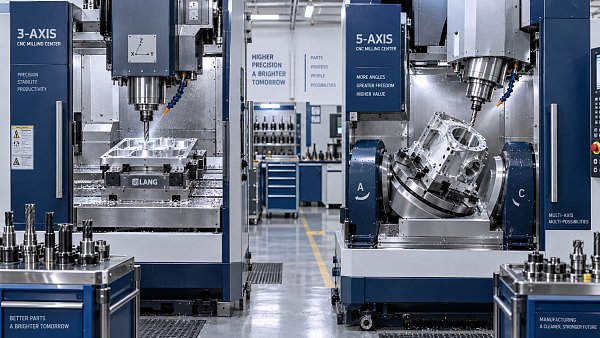
A 3-axis mill moves the cutting tool relative to the workpiece along three linear axes. During a conventional setup, the tool approaches from a fixed orientation. This works well for plates, open pockets, accessible slots, and many housings or brackets. The machine can also produce contoured surfaces by coordinating its linear movements, provided the cutter and holder can reach the surface without interference.
A part with features on several faces does not automatically require 5-axis machining. It may be economical to machine one face, turn the component into another fixture, and continue. If those setups locate reliably and the tolerances between faces are manageable, a 3-axis route can remain competitive even when the finished component looks complicated.
The case for 5-axis becomes stronger when the cutting direction must change to reach angled holes, inclined pockets, or surfaces obstructed by surrounding geometry. Two rotary axes change the orientation between the tool and workpiece. Depending on the machine configuration, the table, the head, or both provide that movement. This creates more options for reaching features and positioning the cutter.
Consider a housing with internal pockets and mounting features on several inclined faces. A 3-axis process may need multiple fixtures, each with its own locating method and tool-access compromises. A 5-axis process may reach several of those faces while retaining the same clamping arrangement. The benefit comes from simplifying the route and preserving feature relationships, rather than from the number of axes itself.
Access still has limits. A holder can collide with a wall even when the tool tip reaches the intended surface. A deep cavity may remain inaccessible, and an undercut may require a special cutter, another process, or a design change. Ask for an assessment of the complete tool assembly, fixture, and machine travel before treating 5-axis capability as proof of manufacturability.
Distinguish indexed machining from simultaneous 5-axis cutting.
Many parts that benefit from a 5-axis machine do not require all five axes to move together during cutting. In indexed machining, often called 3+2 machining, the rotary axes position the part or tool at an angle, then remain fixed while the linear axes perform the cut. This can be an effective route for angled holes, inclined faces, and features distributed around a component.
Simultaneous 5-axis machining changes tool orientation while the cut progresses. It becomes valuable when a surface or passage requires continuous changes in approach direction, or when controlling tool contact along a complex contour improves the process. Impellers and certain sculpted components illustrate this need, although the appropriate strategy still depends on the individual geometry.
That distinction matters when comparing quotations. A proposal for “5-axis machining” might involve indexed positioning, simultaneous cutting, or a combination of both. Ask which features require each mode and what problem the selected strategy solves. Continuous rotary motion adds programming and verification demands; it should have a clear purpose in the manufacturing plan.
Tilting the workpiece can also allow a shorter cutter to reach a feature. A shorter tool overhang can improve stiffness and reduce deflection, which may support better dimensional control and surface finish. However, the benefit depends on the fixture, spindle access, cutting forces, and available tool orientations. A well-supported 3-axis cut can outperform a poorly planned 5-axis operation.
Evaluate accuracy through the setup plan.
One reason to consider 5-axis machining is to reduce errors introduced by repeated unclamping and locating. Every transfer creates another opportunity for chips, burrs, fixture variation, or alignment error to affect the next operation. When critical bores, faces, or locating features must maintain tight relationships across different sides, reducing transfers can make the process easier to control.
This advantage is particularly relevant when the drawing specifies position, perpendicularity, or angular relationships between features machined from different directions. Review those requirements against the proposed datum scheme. A dimension that appears straightforward on the drawing may become difficult if its two reference features are created in separate setups with an uncertain locating relationship.
Five-axis machining introduces its own error sources. Rotary-axis positioning, machine geometry, thermal conditions, tool-center-point calibration, and workpiece location can all influence results. A machine’s published positioning specification does not establish that a finished component will meet its drawing. Accuracy must be assessed across the complete process, including workholding, cutting conditions, and measurement.
Thin walls and flexible components need additional care. Keeping a part in one clamping can preserve alignment, but it cannot prevent movement caused by residual stress or material removal. The process may still require roughing, releasing and reclamping, or a separate finishing operation. Pursuing a single setup at all costs can produce a less stable route than a deliberate sequence of controlled setups.
Inspection should follow the critical feature relationships. In-process probing can help establish work offsets and detect certain deviations, while final inspection determines whether the part meets the specified requirements. Where clamping affects geometry, the measurement condition also matters. A component that measures correctly under restraint may behave differently after release.
Compare the cost of an accepted part.
A machine’s hourly rate is only one element of machining cost. The comparison should include programming, fixtures, setup labor, cutting time, tools, inspection, and the consequences of scrap or rework. A higher machine rate can be offset by fewer setups and simpler workholding. Conversely, additional programming effort may overwhelm those savings when the geometry is easy to machine conventionally.
For a straightforward plate with accessible pockets and holes, 3-axis milling is a strong starting point. There may be little value in occupying a more complex machine if the same operations use similar cutters and take similar time. For a component requiring several angled fixtures, the economics can reverse: fixture preparation and repeated handling may contribute more cost than the cutting itself.
Quantity changes the balance, but it does not dictate a universal answer. In a small batch, avoiding several dedicated fixtures may justify 5-axis machining even if programming takes longer. In repeat production, the cost of dedicated 3-axis fixtures can be spread across more parts, potentially making a conventional route attractive. Stable demand may also justify multi-part workholding or other production arrangements.
Compare the routes at the intended order quantity and at realistic repeat quantities. Separate one-time programming and fixture charges from recurring unit cost. Otherwise, a quotation with a low unit price and substantial tooling charges can appear cheaper than it is, while a route with higher initial engineering effort may look unnecessarily expensive.
Lead time deserves the same treatment. Fewer setups can shorten production, but a heavily scheduled 5-axis machine may have limited availability. Programming, collision checking, fixture preparation, and first-part inspection also affect delivery. Ask for a lead time based on the proposed route and available capacity, especially when the order includes complex simultaneous toolpaths.
Use the quotation to test the process assumptions.
A useful RFQ gives the supplier enough information to choose a route intelligently: the 3D model, a controlled drawing, material requirements, quantities, and clearly identified critical characteristics. Surface finish and edge requirements should be explicit where they affect function. Without that information, competing suppliers may price different interpretations of the same component.
Request a brief explanation of the setup plan alongside the price. It need not disclose proprietary toolpaths. It should establish how the part will be located, which features will be machined together, and where transfers occur. For a difficult component, the following questions can expose meaningful differences between proposals:
- Which features drive the choice of 3-axis, indexed 3+2, or simultaneous 5-axis machining?
- How many clamping operations are planned, and how will critical datums transfer between them?
- Does any feature require an unusually long cutter, special tooling, or restricted machine orientation?
- How will the supplier inspect the relationships most likely to be affected by repositioning?
- Which programming and fixture costs will recur on a repeat order?
Evaluate the answers for consistency. A proposal that promises one-setup completion should explain how clamping surfaces and the underside will be finished. A claim of improved accuracy should identify which transfer errors disappear and how the remaining errors are controlled. A lower price should be assessed against the same material, finish, inspection, and delivery requirements.
Supplier capability matters most where the process becomes demanding. Access to a 5-axis machine alone does not establish competence in complex machining. Suitable CAM strategies, a verified postprocessor, collision simulation, appropriate workholding, and a credible inspection plan all contribute to execution. For a repeat program with difficult geometry, relevant sample work or a first-article evaluation provides more useful evidence than a machine list alone.
There is also room to simplify the design before choosing the process. An angled hole, inaccessible internal corner, or restrictive pocket may drive disproportionate manufacturing effort. If the feature has no essential functional purpose, changing its orientation or providing more tool clearance can make a simpler route viable. Functional requirements should govern that discussion; tolerances should be relaxed only where the design allows it.
A practical decision follows from the drawing. Begin with 3-axis milling when access is straightforward and the setup plan controls the required relationships. Move toward indexed 3+2 when several approach angles can be reached efficiently within one clamping arrangement. Specify simultaneous 5-axis cutting where continuous orientation changes solve a defined access or surface-generation problem. When two routes remain credible, compare their setup plans, inspection methods, and total costs at the actual order quantity. The stronger choice is the route that can repeatedly deliver the required part with a clear, defensible process.
The Archive Newsletter
Critical industrial intelligence delivered every Tuesday. Peer-reviewed summaries of the week's most impactful logistics and market shifts.